
STEP 1: Weld thickness
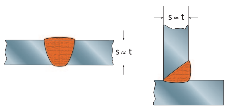
The first step is to determine what the thickness of the weld should and can be. For stump welds the rule of thumb is: weld thickness (s) is equal to material thickness (t), providing that the material properties are similar.
Stump weld
s = t
For a standard corner weld the rule of thumb is as follows:
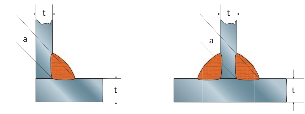
Single-sided corner weld
a = 0,7 x t (S235)
a = 0,8 x t (S355)
Wherein t is the thinnest plate to be welded.
Double-sided corner weld
Since a double-sided weld is obviously stronger than a single sided weld, the weld does not need to be as thick on either side. Therefore, the weld thickness can be:
a = 0,5 x t (S235)
a = 0,6 x t (S355)
Wherein t is the thinnest plate to be welded.
The weld thickness ought to be noted on the drawing of the weld assembly, alongside with what type of weld to use. This is, most commonly, determined by the engineer (in accordance with the welder when necessary). For the welding annotation for drawings check out: Welding annotations (standard welding symbols)
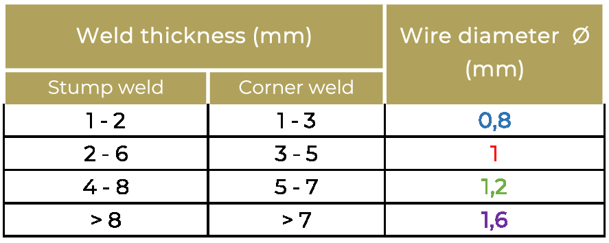
STEP 2: Wire diameter
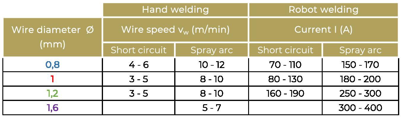
Once the weld thickness is determined, a wire diameter can be chosen. Depending on the weld thickness and the type of weld. See the table below:
STEP 3: Wire speed and Current
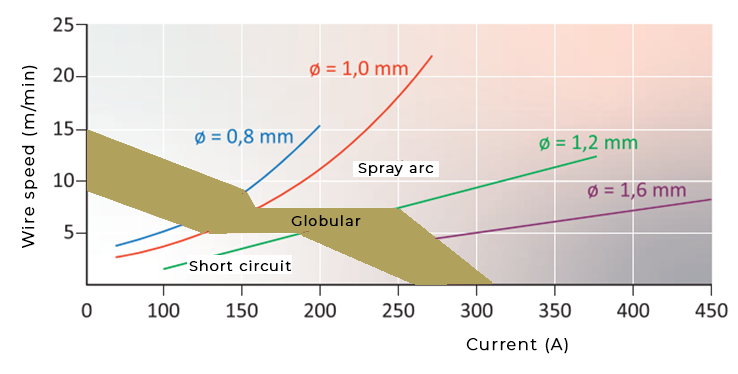
For determining the wire speed and amperage, we first need to distinguish three main welding techniques.
The three techniques describe the manner in which metal is transferred from the wire to the weld pool. In short circuiting metal transfer, also known as ”Short Arc”, ”Dip Transfer”, and ”Microwire”,metal transfer occurs when an electrical short circuit is established. This occurs as the molten metal at the end of the wire, touches the molten weld pool. In spray arc welding, small molten drops of metal are detached from the tip of the wire and projected by electromagnetic forces towards the weld pool. Globular transfer occurs when the drops of metal are quite large and move toward the weld pool under the influence of gravity. Factors that determine the manner of metal transfer are the welding current, wire size, arc length(voltage), power supply characteristics, and shielding gas.
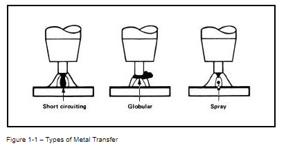
source: https://www.esabna.com/euweb/mig_handbook/592mig1_3.htm
Short Circuit
This welding technique is particularly useful for joining thin materials in any position, thick materials in the vertical and overhead position, and for filling large gaps. Short arc welding should also be used where minimum distortion of the work piece is a requirement.
Globular Transfer
As the welding current and voltage are increased above the maximum recommended for short arc welding, metal transfer will begin to take on a different appearance. This welding technique is commonly known as globular transfer, with metal transferring through the arc. Usually, the drops of molten metal have a greater diameter than the wire itself. This mode of metal transfer can be erratic, with spatter and occasional short circuiting being common.
Spray arc
Spray arc welding can produce high deposition rates of weld metal. This welding technique is generally used for joining materials 2.4mm and greater in thickness. Except when welding aluminum or copper, the spray arc process is generally restricted to welding in the flat position only because of the large weld puddle. However, mild steel can be welded out of position with this technique when small weld puddles are used; generally with a 0.8 mm or 1 mm diameter wires.
When the welding technique is chosen, the following lookup table and rule of thumb can provide the correct wire speed and amperage, for welding by hand or with a robot.
Rule of thumb:
Current (A) = 17 x Ø2 x (vw + 2)
Ø = wire diameter in (mm)
vw = Wire speed in (m/min)
STEP 4: Voltage
As a rule of thumb, the following formula can be used:
U = (0,05 x I) + 14
U = voltage in (V)
I = current in (A)
STEP 5: Weld travel speed
This step is more relevant for robot welding then for welding by hand, as this is somewhat hard to determine when welding by hand. This is based more on experience than an abstract number. Yet to be as complete as possible, in this article a rule of thumb for the welding travel speed will be given for both.
Theoretical formula:
vt = (80 x Ø2 ) / ( a2 x vw )
vt = welding travel speed (cm/min)
Ø = wire diameter in (mm)
a = weld thickness in (mm)
vw = Wire speed in (m/min)
Rule of thumb:
Hand welding 20 – 70 cm/min
Robot welding max. 200 cm/min
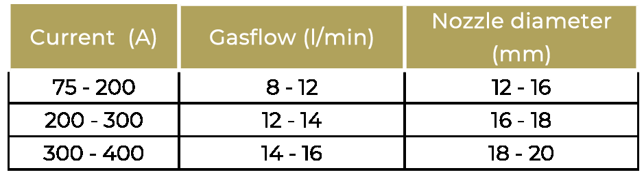
STEP 6: Gas flow and nozzle diameter
When welding with gas, the flow and the nozzle have to be adjusted, according to the earlier specified amperage.
( STEP 7: Preheating)
For most situations this would be all you need to know, to start welding. For welding thicker metals, it could be wise to preheat the metal.
Preheating in welding is used to help ensure weld quality and reduce the occurrence of cracking and other problems that can result in costly rework. Welding preheat is commonly used before welding steel or steel alloy pipes or plates that are 25 mm thick or more. See additional STEP 7 in a separate article: Preheating for welding
Add a comment